Power and Energy.
Scoll down for a new presentation on triple harmonic injection.
The Benefits
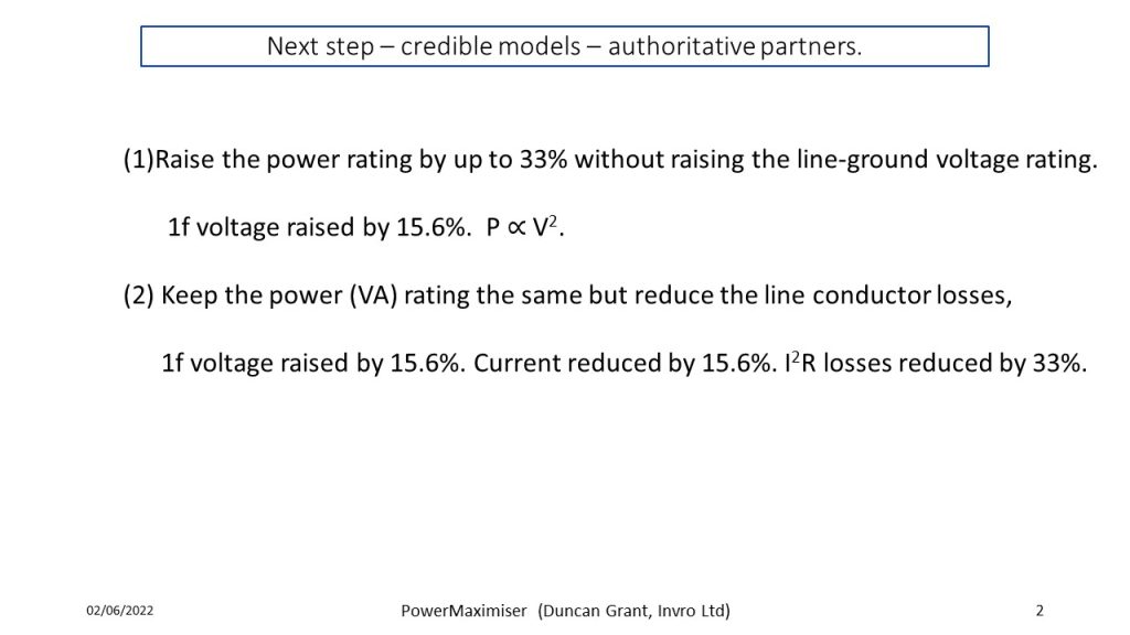
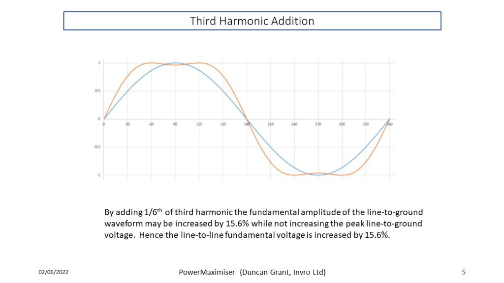
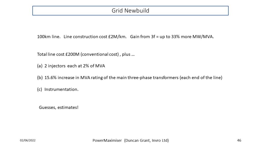
Triple frequency injection adds up to 33% to the power rating of a transmission line.
Or keep the power the same and swap Amps for Volts to reduce resistive line losses by up to 33%
Who should be interested in this?
Grid and distribution system operators.
Any business making equipment for these organisations.
Any energy business looking to transition from fossil fuels to renewable electrical energy.
Constructors of vehicles and power systems for ships aircraft and land vehicles where weight and efficiency matter.
Nations looking to install a long distance power transmission system.
Subsea transmission system operators and equipment providers for these.
Transformer manufacturers.
Cable makers.
Power station (at all levels) designers.
Background
We have invented a triple harmonic injector which makes it easy to set up a power transmission system based on the third harmonic injection concept. We have filed a UK patent application and received an encouraging examiner's report. We have advanced the patent application to the PCT stage. (See Patents). We continue to develop other ideas which will make this technology a practical proposition.
“Plug and Play”
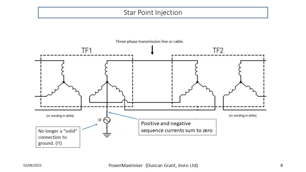
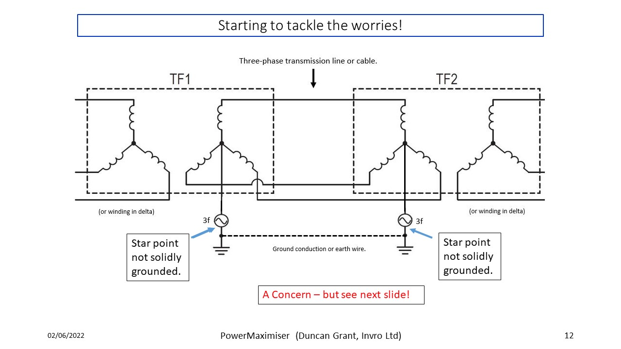
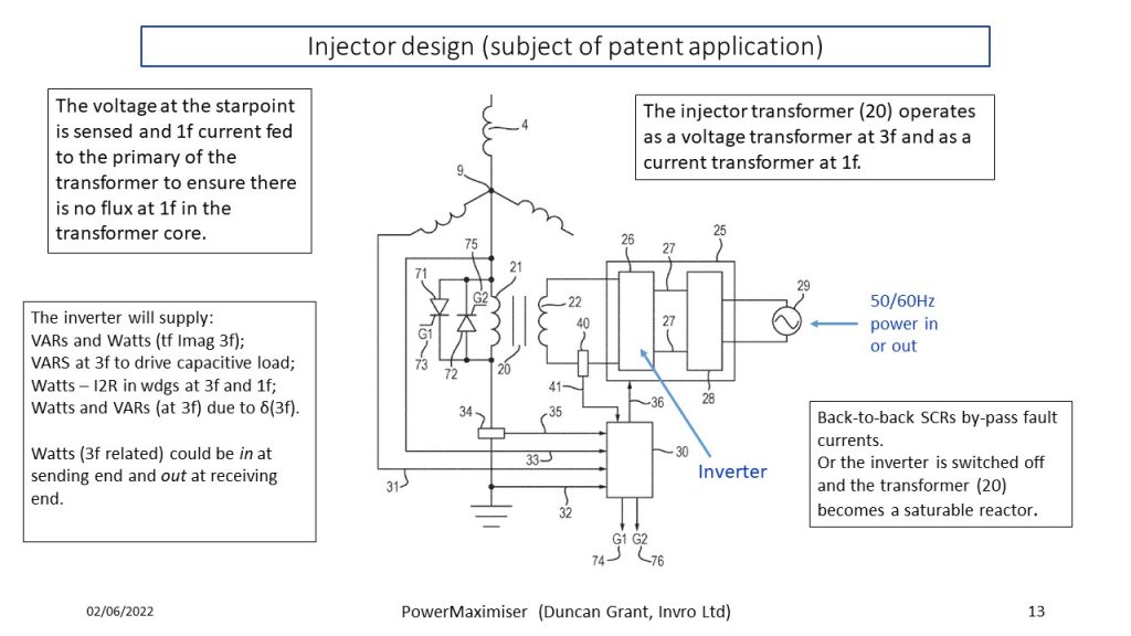
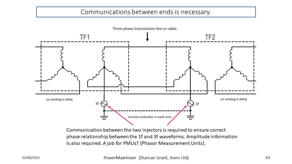
Having discussed this technology extensively with potential users (e.g. grid and distribution system operators) the message we get back is that this is a great idea but we have firm views about how we like to operate (e.g. star points solidly grounded). The star point driver technology (see Patents) is the key to overcoming this objection. It makes the start points of the transformers look like a solid ground at fundamental frequency while injecting a triple frequency voltage waveform. It handles balanced and unbalanced loads on the three phase system. It handles faults by behaving as a solid connection to ground while the fault is detected and protection equipment operates. Other matters need consideration. The power system three-phase transformers have to be coordinated with the new capabilities of the transmission system. The cost and the need to make changes depend on whether the system is new or the technology is being retrofitted to existing transmission lines. We have the answers. With the plug-and-play injectors in place these issues become secondary considerations.
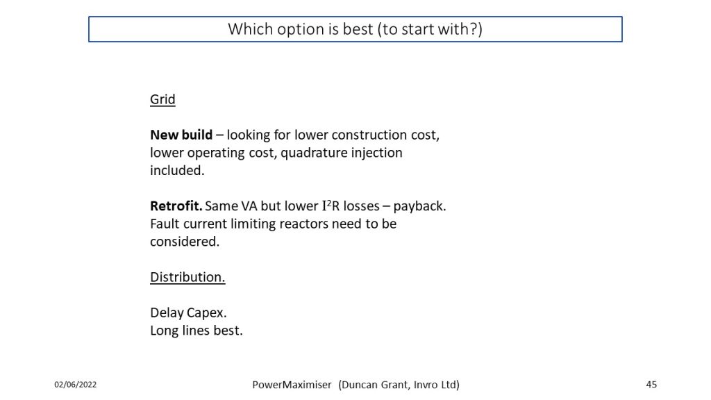
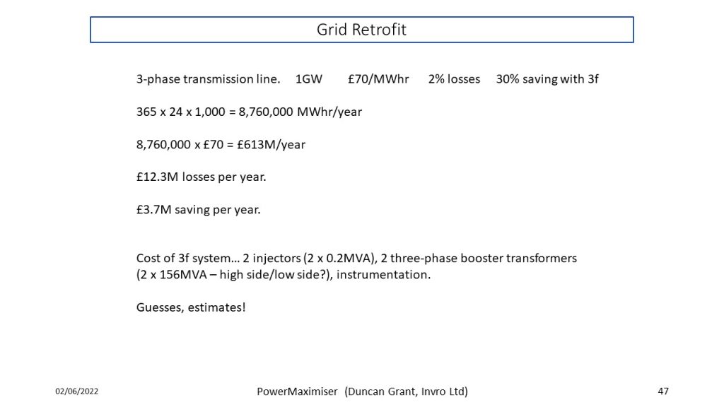
Power capability increase or energy saving - a quick payback?
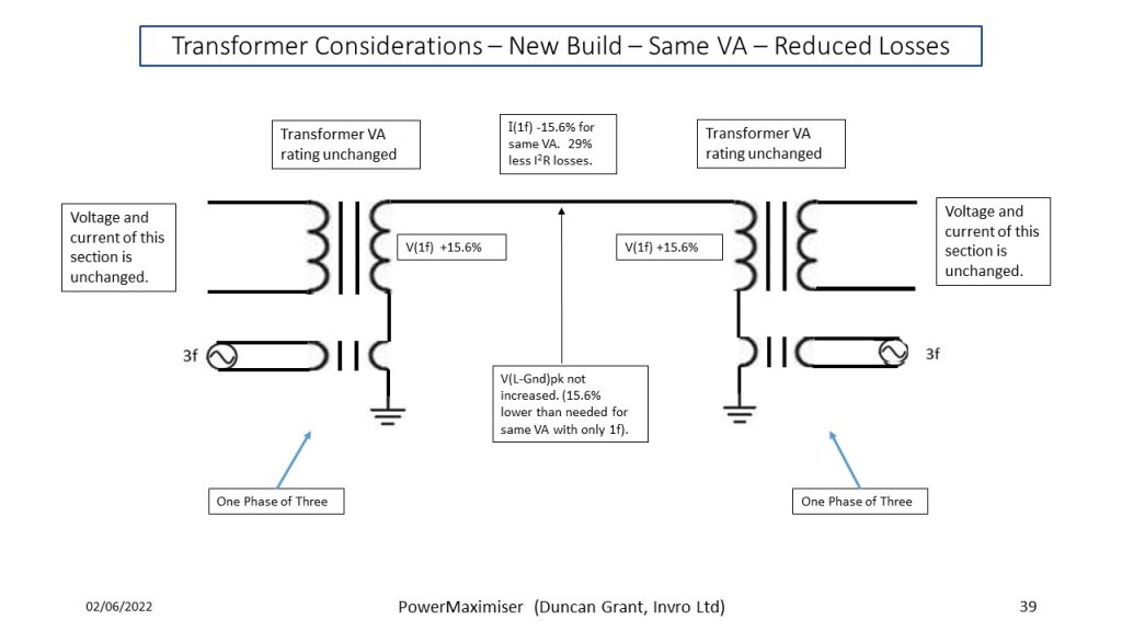
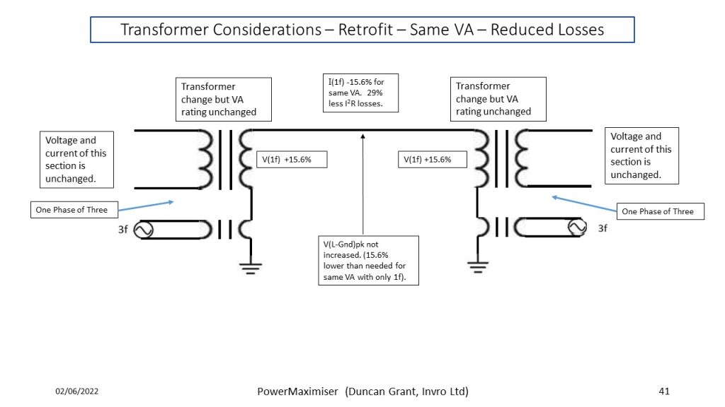
Instead of using the third harmonic system to increase the power rating, it can be used to raise the effective voltage by 15% (without increasing peak line-to-ground voltage) and thus to reduce the current by 15% for the same power transmission. I2R losses in the lines and transformer windings will thereby be reduced by 30%.
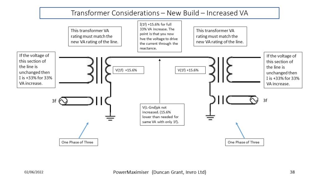
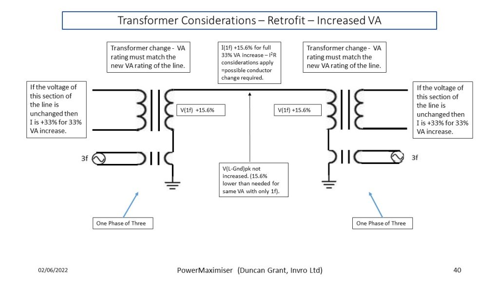
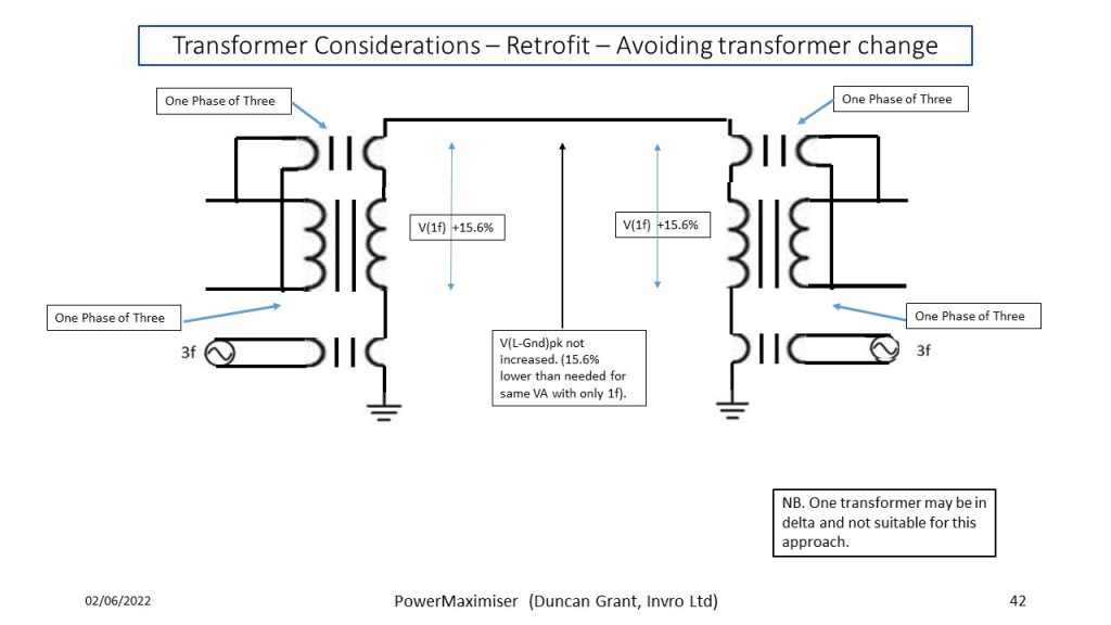
Power loss in a transmission system consisting of transformers and transmission line can be as high as 5% (IEC publication "Efficient Electrical Energy Transmission and Distribution". 2007). If we assume that the I2R losses account for 4% of losses then a 30% saving in I2R losses would give a 1.2% power saving. For a 100MW system the power saving at full power would be 1.2MW. Over a year that would represent an energy saving of 10,512 MWhr. Assuming a wholesale electricity price of £50/MWhr the third harmonic injection system could save approximately £0.5M per year. It is early days to put a price on the third harmonic injection system but these calculations give an indication that the payback time may be quite short. In a new build situation the transformer windings can be chosen to match the requirements of the triple harmonic injection system. In a retrofit situation, one transformer may need changing since a common arrangement for the transformers is to configure the sending end transformer winding in star and the receiving end transformer winding in delta and hence the payback time in that situation would be somewhat longer but should still be attractive.
Comparison of Triple Harmonic Injection (THI) and Quadrature Voltage Injection (QVI)
Quadrature Voltage Injection (QVI)
QVI technology is based on the injection of a fundamental frequency voltage waveform into each of the three lines of the three phase transmission system. An injector unit is connected in series with each line. The units are mainly intended to inject quadrature voltage to promote the flow of in-phase current in the wanted power flow direction. In-phase voltage could be injected to manage VAR flow so that the full current carrying capacity of the wires is used to transmit power but this does not seem to be done. Presumably this is because customer-derived VAR flow is best dealt with by other means. Power flow in a transmission line is approximately given by:
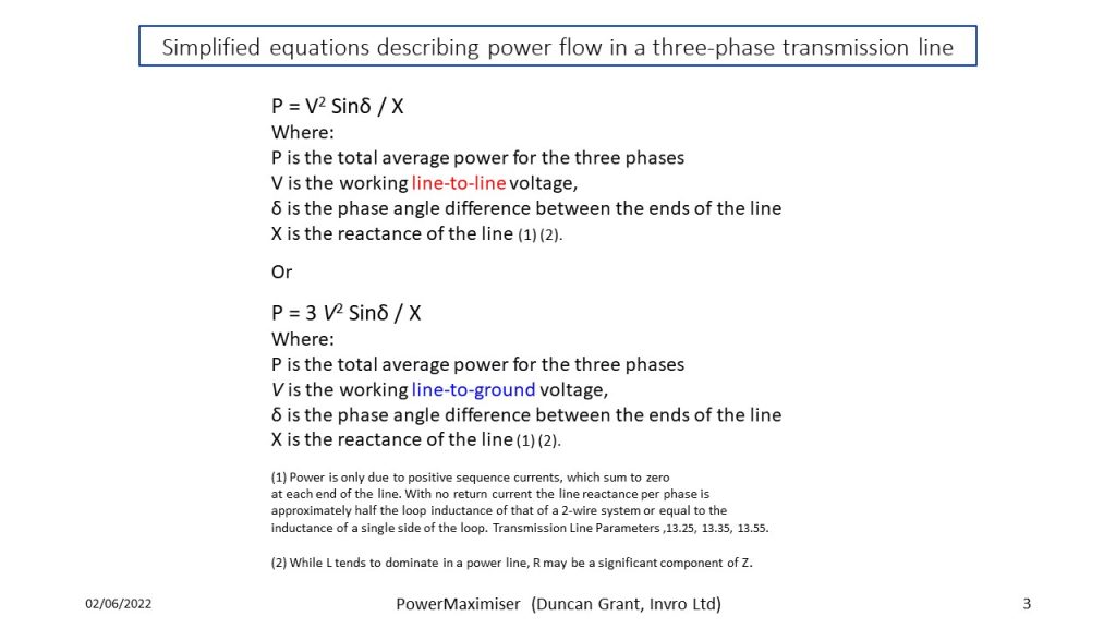
P = V2 Sinδ / X , where V is the working line-to-line voltage, δ is the phase angle difference between the ends of the line and X is the reactance of the line. QVI can also be viewed as manipulating X (impedance Z in the more complete power flow equations). It can also be seen as increasing delta (with fast removal for stability management).
Power-electronic, series-connected quadrature voltage injectors are undoubtedly an advance on the traditional transformer-based quadrature voltage injectors. The QVI proposition is that the widespread use of such injectors permits better manipulation of power flow in systems where multiple transmission paths are available. Overloaded lines can be relieved while under-used lines can be given more load. The maximum power capability of any individual line is however unchanged.
Triple Harmonic Injection (THI)
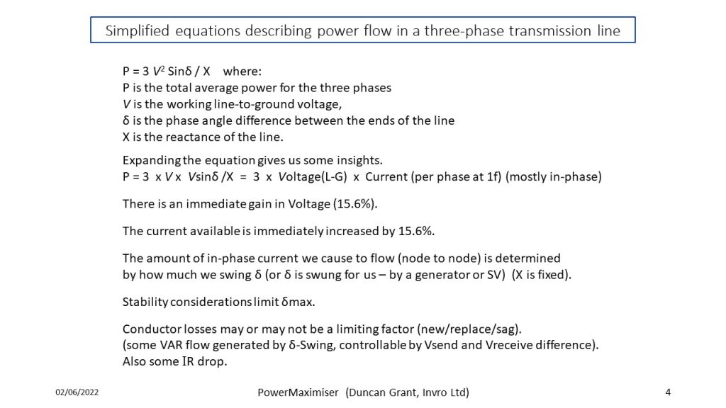
The THI approach is to increase the maximum power flow available in a single three-phase transmission line by increasing the value of V in the equation P = V2 Sinδ / X without increasing the line-to ground voltage. The THI proposition is that the power capacity of a transmission line (or cable) can be increased by up to 33% without changing the lines. Where QVI looks to move the utilisation of a multi-path transmission network closer to 100%, THI looks to move the power handling capacity of a single three-phase transmission line closer to 133%. THI has a second mode of operation in which the VA rating kept the same. I is reduced in the same proportion as V is increased thus reducing I2R losses by 33% (or allowing the use of thinner, lighter wire).
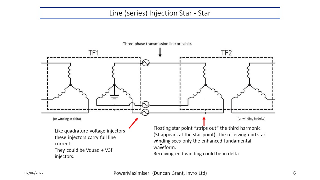
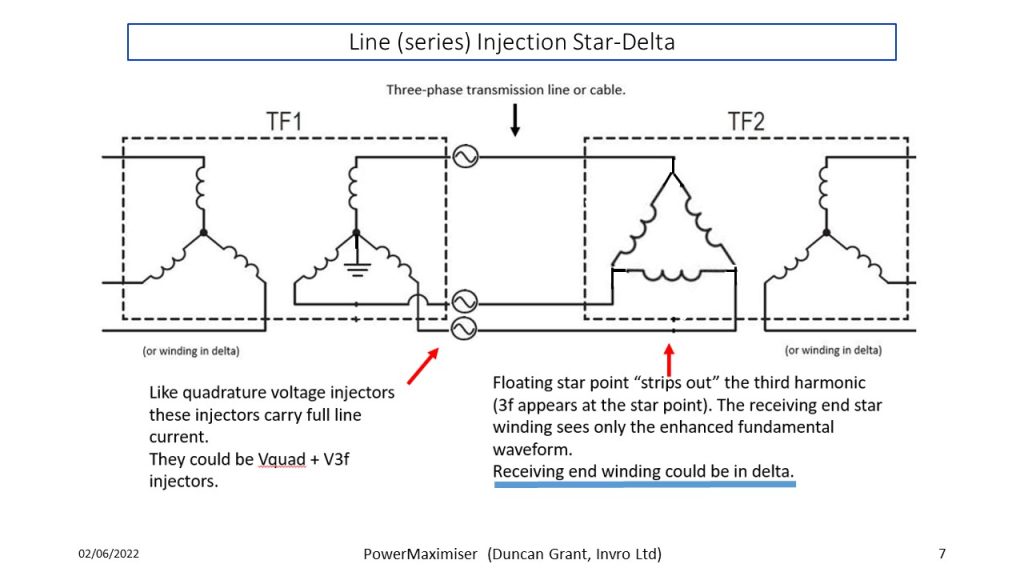
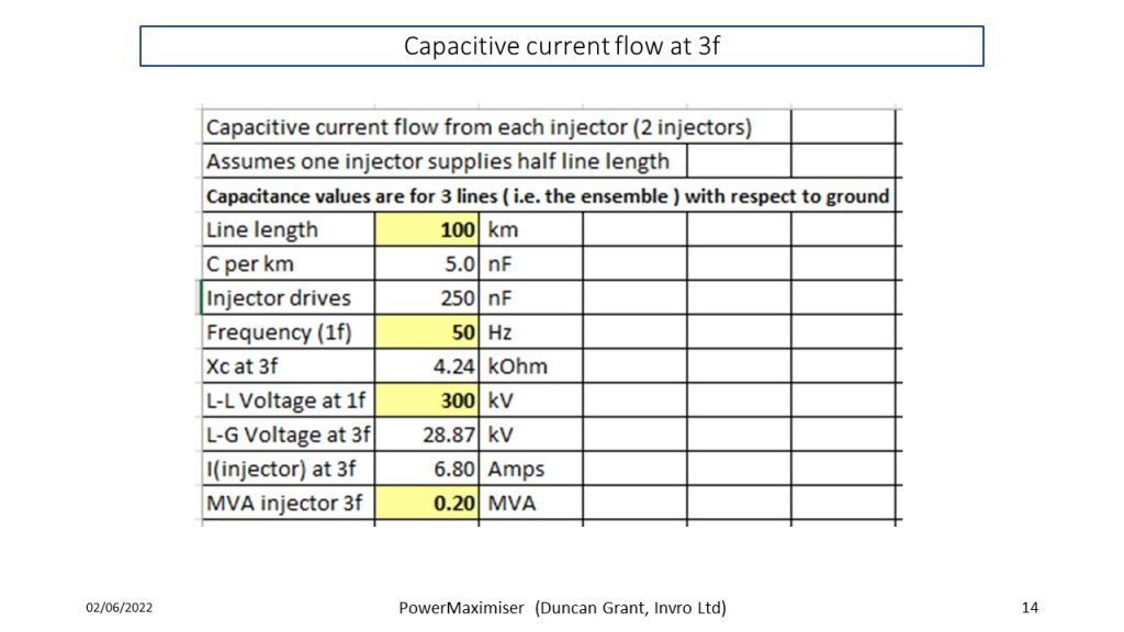
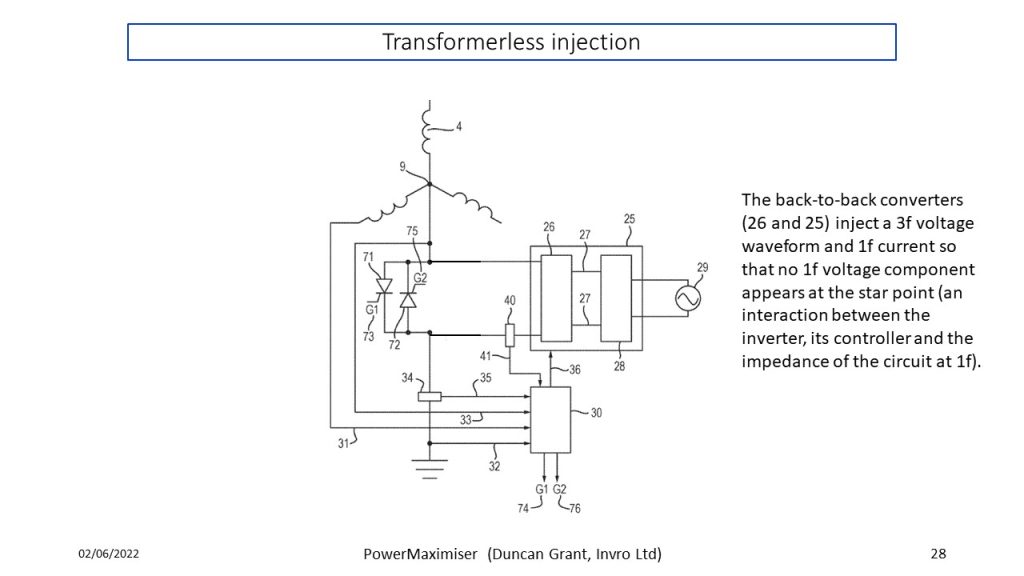
THI injectors have a voltage rating of 1/6th that of line-ground voltage rating of the transmission line. The current that the injectors carry in TH! system is will be composed of a small triple frequency current associated with some power flow, a triple frequency current due to line-to-ground capacitance and a fundamental frequency zero-sequence current due to any unbalanced load not dealt with elsewhere in the system (e.g. by a delta transformer winding). The QVI injectors carry the full line current at whatever quadrature voltage is injected. Hence it is difficult without modelling to compare VA ratings. THI uses two injectors while QVI uses three. THI injectors are at ground potential while the QVI injectors are at line potential. QVI injectors use capacitors which in some embodiments look bulky. THI injectors use a single-phase transformer with associated inverter (size to be determined but not likely to be large). The THI injectors could be smaller still if they were made to a transformerless design (foregoing some of the benefits of a transformer-based design).
Why star-point injection is used in THI and possible synergy with QVI.
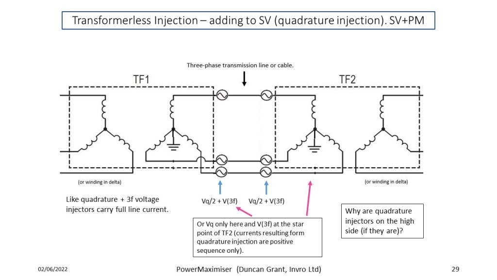
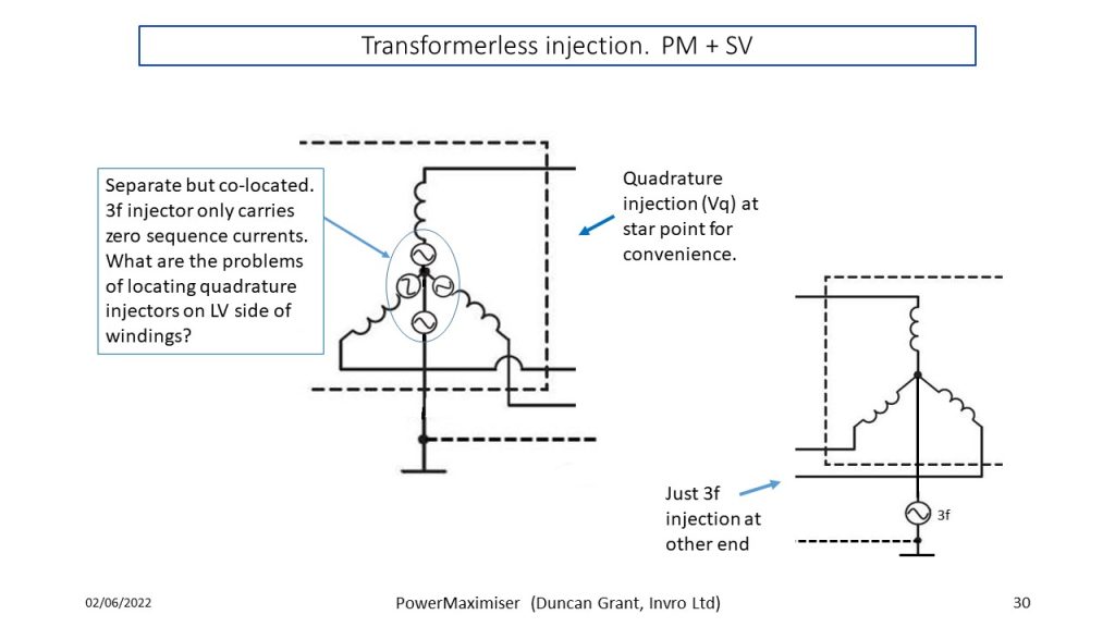
The triple-harmonic injection principle employed by THI can be implemented by injecting the third harmonic either at the star point of the three phase transformers at each end of the line or by injecting the third harmonic into each line at each end with series injectors. The series injector approach has not been chosen because full line current will flow through each injector requiring each injector to have a VA rating of V(line-to-ground) x 1/6 x I(line). There could be synergy with the QVI concept if the QVI injectors were split into two (of half voltage at fundamental frequency, one injector at each end of the line). THI uses star-point injectors because at the fundamental frequency they carry only zero sequence current (when it arises). QVI star-point injectors are at ground potential and inject a cophasal, triple-frequency waveform into all three phases. The injector can be modified to also inject fundamental frequency quadrature voltage in the three lines for power flow control. The present Power Maximiser patent application can be built on to cover that arrangement.
Summary.
QVI. There is no doubt that power electronics has brought series injection of quadrature voltage to the fore.
QVI is about steering power so that underused lines may be used to their full power (or VA) limit.
THI Is about increasing the maximum power capacity of new build or existing lines or cable – up to 133%
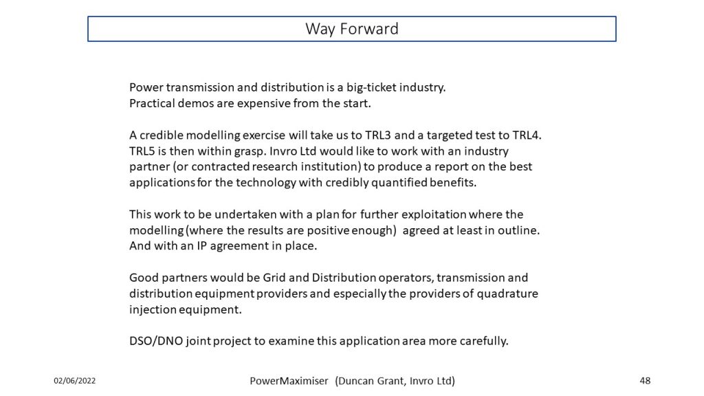
THI needs an opportunity to show its merits – first by modelling and then with a pilot system.
THI and QVI. Synergy between QVI and THI should be explored ( QVI + THI and THI + QVI ).
If you are interested in partnering with us on this project and would like more information please do get in touch (see Contact Us).
A Presentation on The Triple Harmonic Injection Concept - Challenges and Solutions
Highlights
The maths - slide 4.
The wavefom - slide 5.
Basic single-ended operation - slides 6-8.
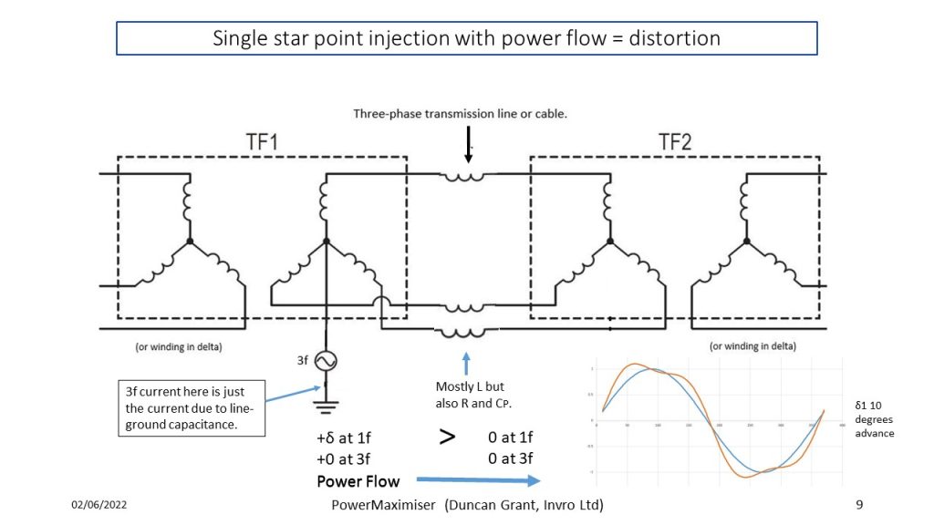
The challenge of maintaining the required waveshape - slide 9.
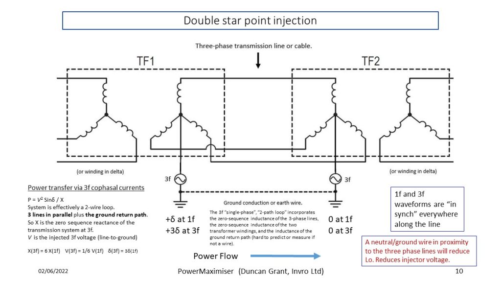
Double-ended operation - slides 10-12.
Patent application 1 - keeping the starpoint at ground potential while injecting 3f - slide 13.
The VA at 3f is manageable - slide 14.
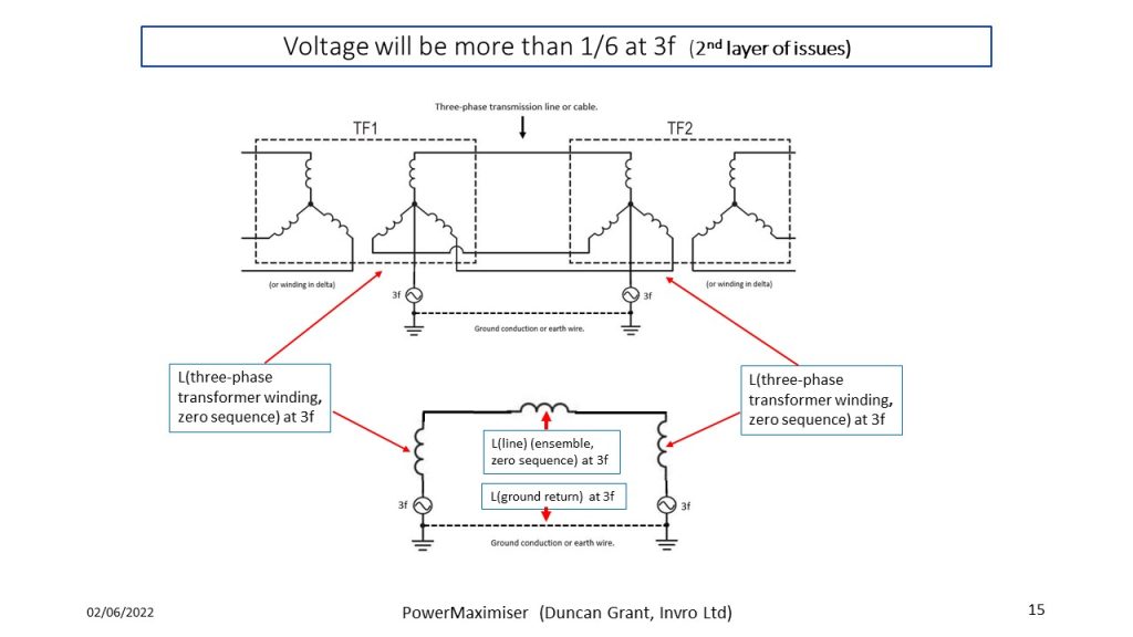
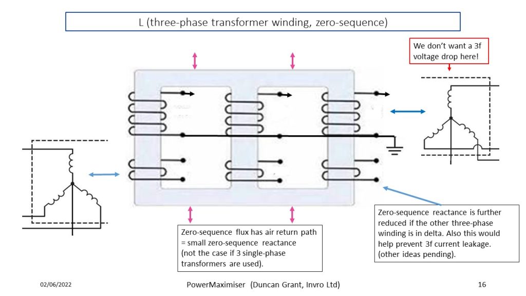
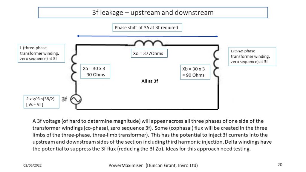
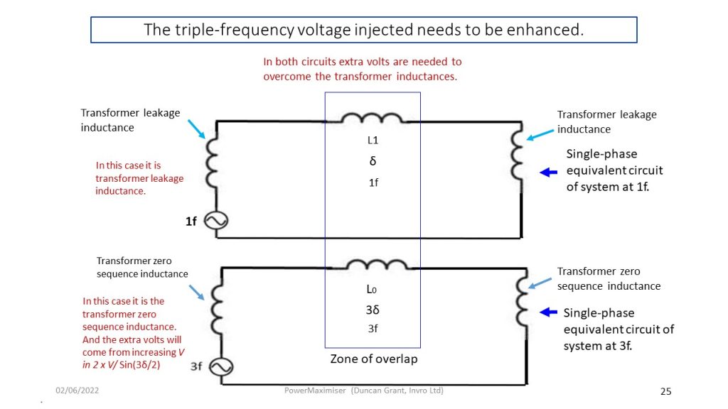
Transformer leakage inductance needs consideration too - slides 15, 16.
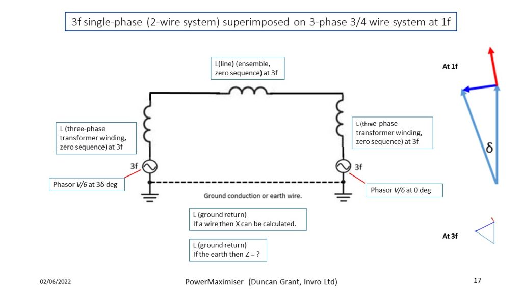
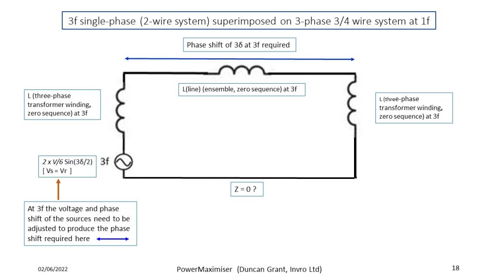
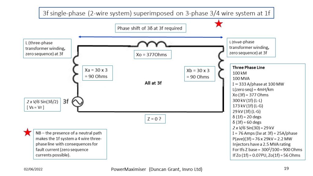
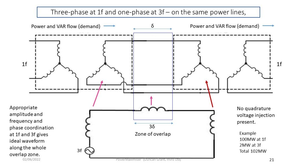
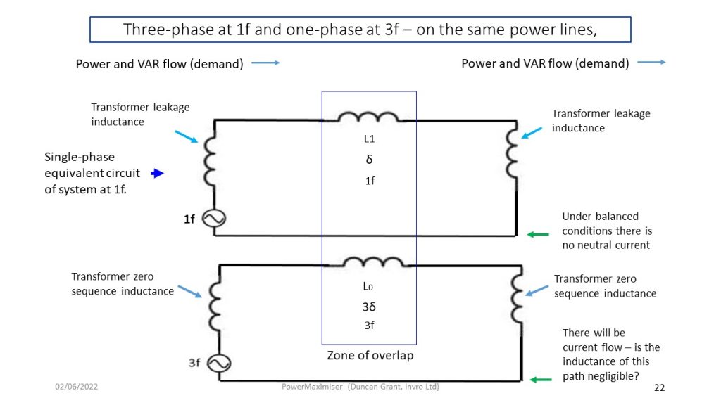
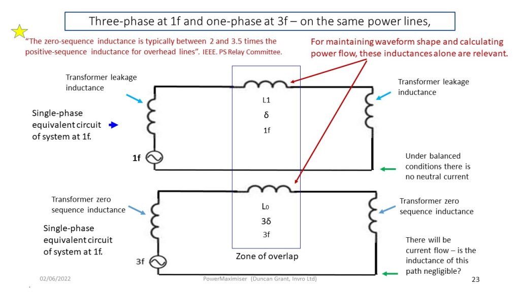
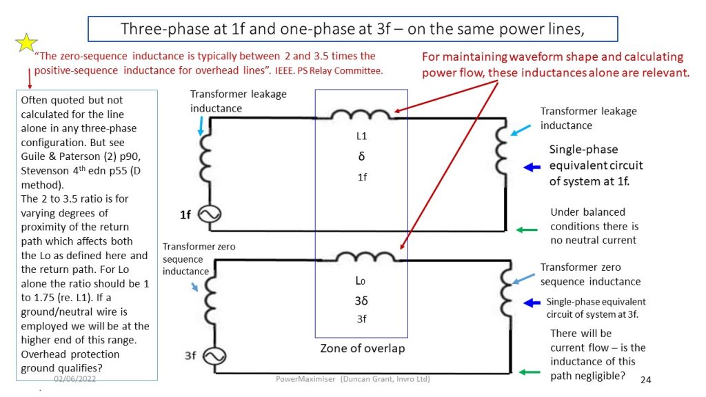
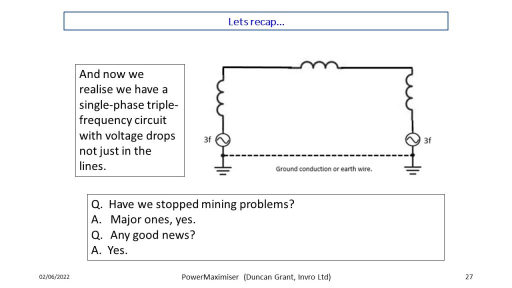
Consider the arrangement to be three-phase at 1f plus single phase at 3f - slides 17-25.
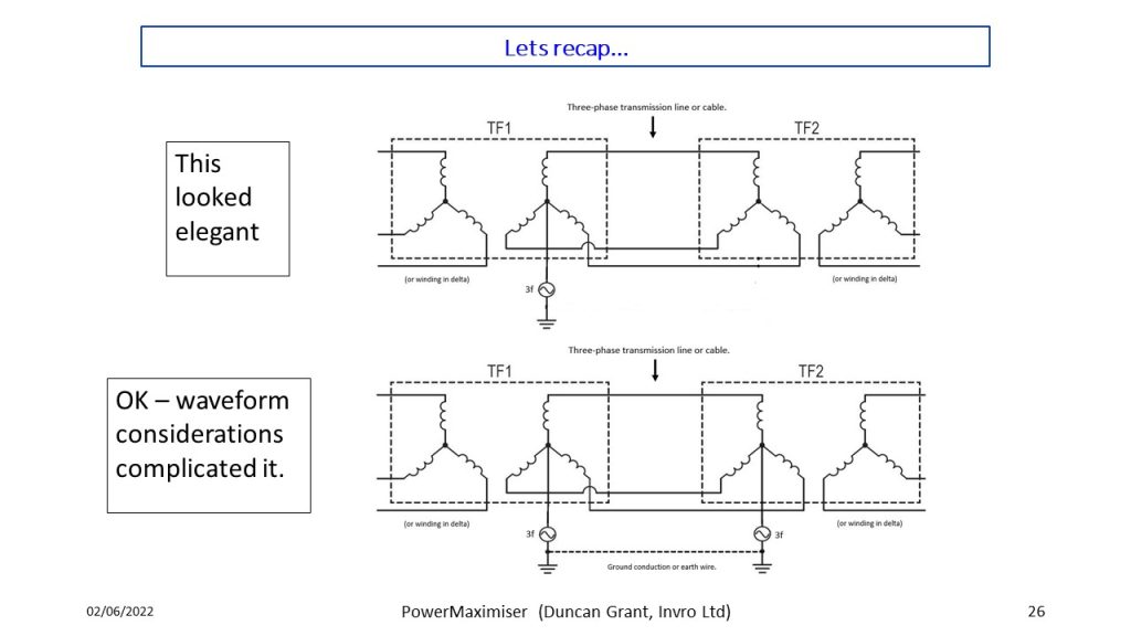
Recap= slides 26, 27.
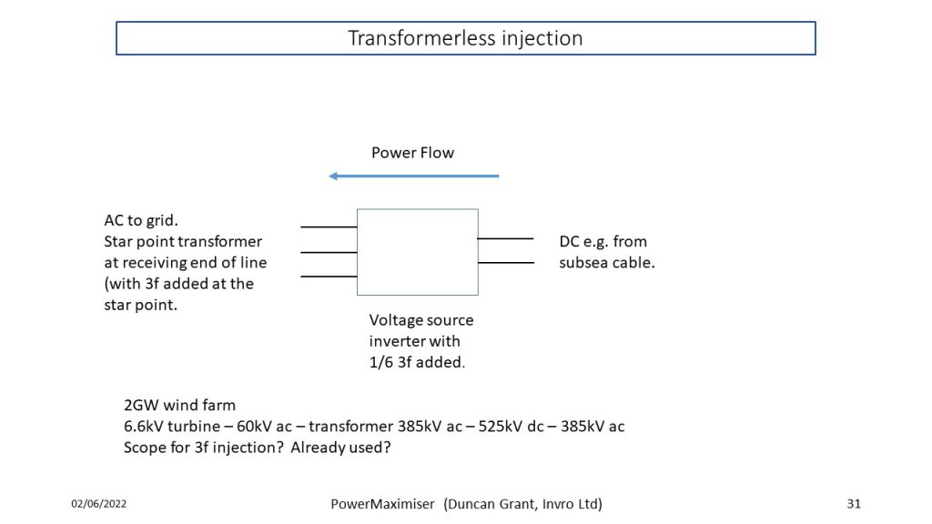
Transformerless injectors, combined with quadrature voltage injection - slides 28-31.
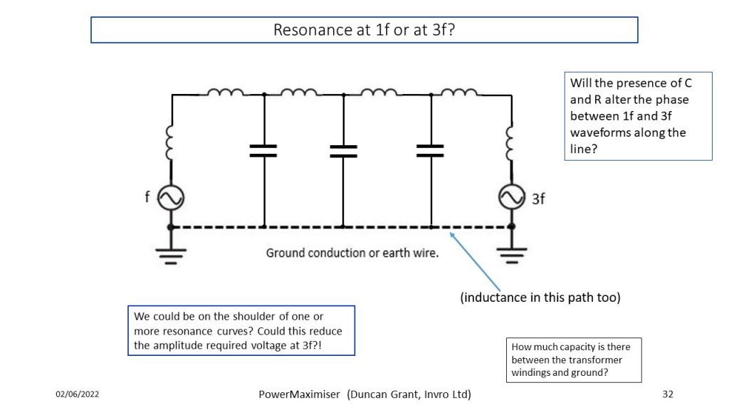
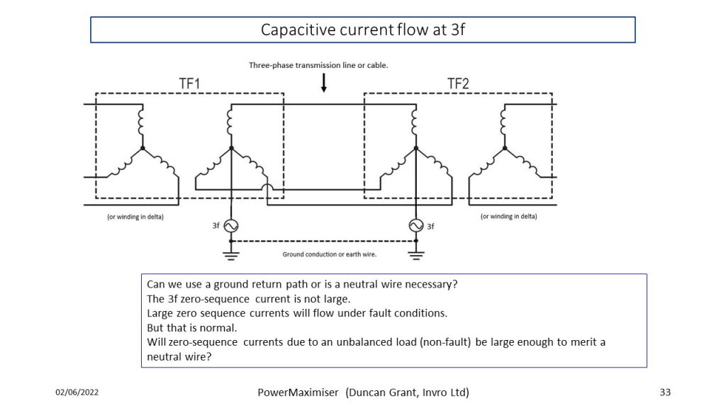
Capacitance considerations - slides 32, 33.
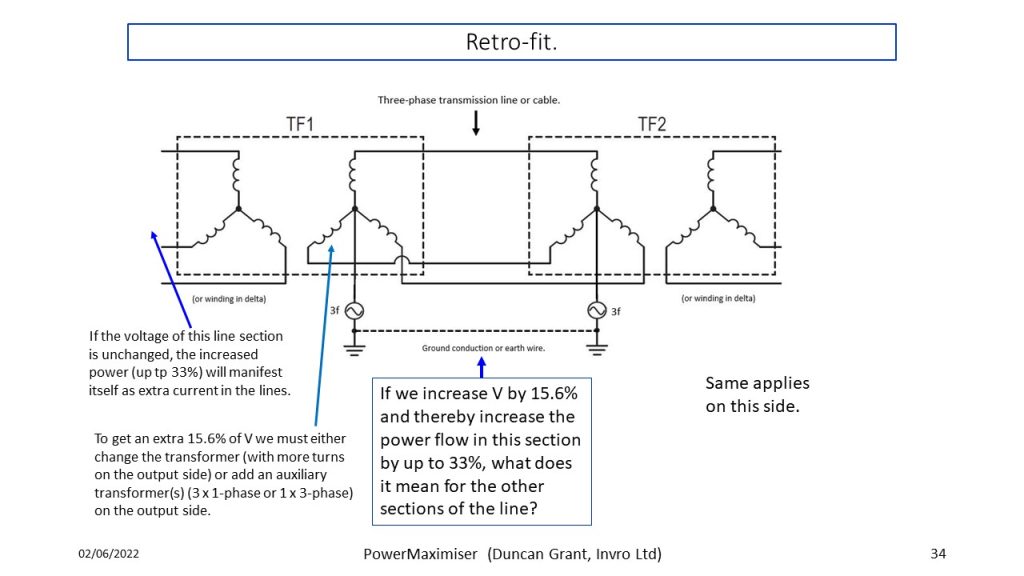
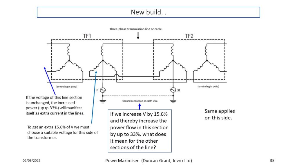
Retrofit vs new build - slides 34-35.
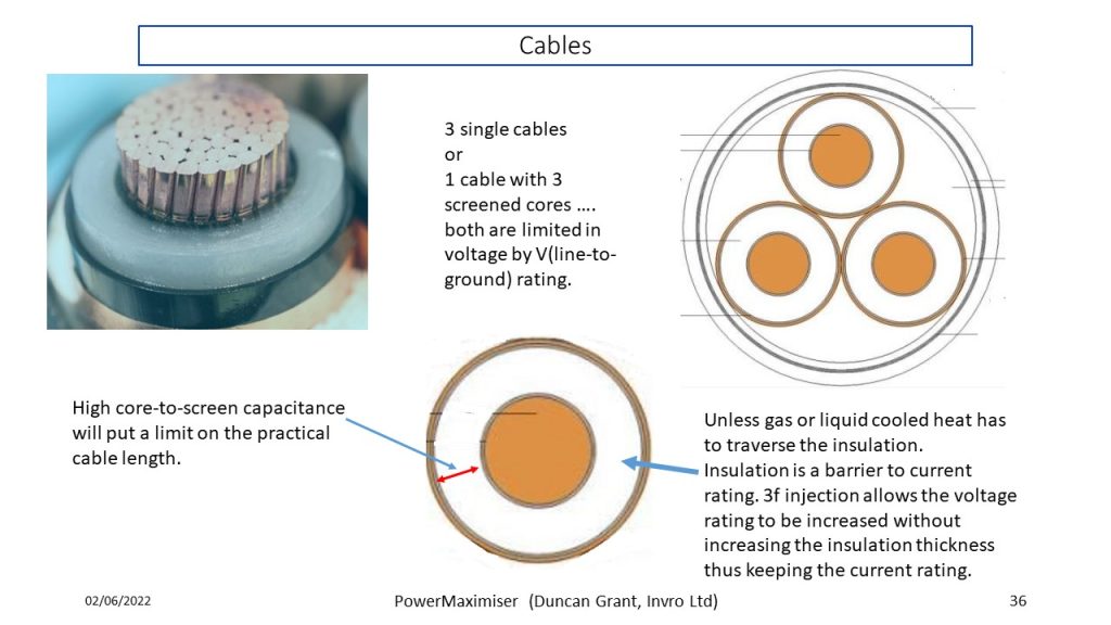
Cables - slide 36.
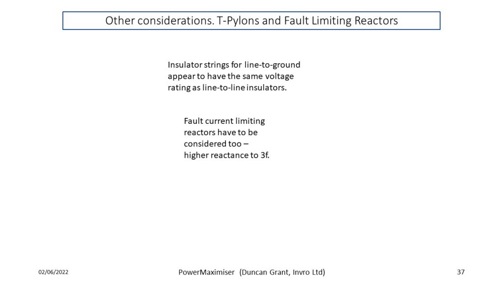
Various topics - slides 37-48.
